128i Car Stereo Upgrade

Project Overview

  • I want to install a backup camera
  • I want to be able to use Carplay
  • I also want to use the buttons on the steering wheel.

Current situation

  • BMW Professional Radio
    • No phone integration
    • No satellite radio
    • No Bluetooth
    • No MOST (fibre optic) unit.

Work content

  • Rear camera
    • Install camera
    • Wiring: Camera power, video input and rear signal wire to car stereo
  • Car stereo
    • Wiring: Connect car stereo to car body
      • Conversion adapter settings
    • Enable steering wheel buttons
      • CANBUS conversion
      • Set corresponding buttons on car stereo
    • Make use of AUX in the center of the car
      • Convert to Line input?

Equipment Expenses

  • Back-up camera
    • LIBEYAMA Trunk handle type
  • Car stereo
    • Main unit ATOTO F7 XE Single Din
    • Single Din faceplate METRA 99-9306B
    • Conversion cable RED WOLF
    • Antenna line conversion cable Fakra
    • CANBUS conversion Metra ASWC-1
    • AUX conversion (carry-over?)

problem

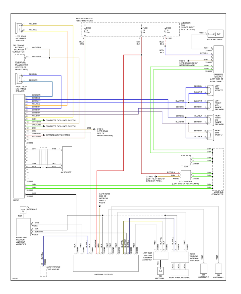
Back-up camera routing

  • Routing from the trunk to the inside of the vehicle. Does not pass through a rubber tube.
  • The route into the vehicle goes through the storage space in the top cover, under the top cover, and from behind the rear seat.

Back-up camera power

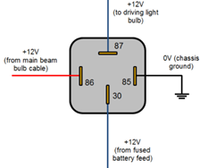
The current from the reverse signal alone is not enough. Use a general-purpose relay to supply 12V directly.

  • Today’s pin #30: From the constant power battery terminal.
  • Pin #85: Body ground
  • Pin #86: Signal line connected to the tail light reverse line
  • Pin #87: Camera positive terminal

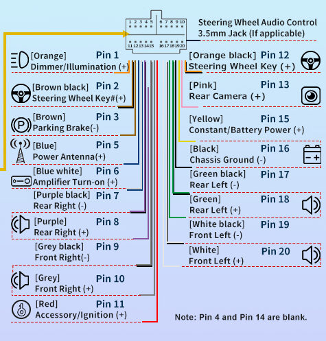
Continuous power supply for car stereo

Car stereos require a constant 12v power supply, but the 16-pin connector from the car body does not receive constant power.
Continuous power is obtained from the fuse box. Free slot #85

Screen flickering

Disconnect the backlight input line

Document

16pn connector

Pin
Number
Pin
Name
DescriptionConnection
1RR+Audio Output8 Purple
2RF+Audio Output10 Grey
3LF+Audio Output20 White
4LR+Audio Output18 Green
5RR- 7 Purple Black
6RF- 9 Grey Black
7LF- 19 White Black
8LR- 17 Green Black
9CAN-Low  Input/OutputASWC-1 Blue/Pink
10Remote_Mute Input 
11CAN-High   Input/OutputASWC-1 pink
12 GND 16 Black ASWC-1 Black
13RAD_ON (Antenna)output5 Blue
14KL58G (Backlight)Input 
15ACCS Gateway_UART_RxDInput11 Red ASWC-1 Red
16   Input 

12 pin B connector

Pin
Number
Pin
Name
Description
1MIC+Input
4Gateway_UART_TxDOutput
6MIC GND 
9Radio_UART_RxDInput
11Radio_UART_TxDOutput

12 pin C connector

Pin
Number
Pin
Name
Description
2AUX_AF_LInput
5MIC Shield 
6MONO+Input
7AUX_AF_RInput
8AUX_AF_GND 
11AUX_AF_SHIELD 
12MONO- 

Aux input to Line in. split grounding cable to 2.